Last updated: 3rd December 2024
Conversion to 12v
Why bother to change your Austin Seven to 12 Volt? Well the easiest way of answering the question is to set out the pros and cons of doing the conversion.
The advantages- 12 volt produces far better headlights than 6 volt.
- 12 volt produces better rear/stop lights
- Running the Austin Seven dynamo at 12 volt REDUCES the heat generated by it and is capable of charging the battery whilst the headlights are on.
- 12 volt components are readily available new, ‘off the shelf’ anywhere in the UK.
- 12 volt flashers are also easier to add to the car, car accessory shops are easier to find than motorbike shops, the normal source of 6 volt items.
- Putting 12 volt through the starter motor makes starting so much easier.
- The horn, operating on 12 volt, is clearer and more audible.
- 12 volt accessories, map lamps, mobile phone charging etc. can
be easily achieved
The disadvantages
- The car is no longer original specification.
- Some modification to the wiring is necessary for those components that still work on 6 volt (wiper and trafficators) unless 12 volt versions are found and replace the 6 volt ones.
- Some early rear light/brake light units will need modification to take a dual filament stop / rear light bulb.
- I can’t think of any others!
There are several methods to achieve the change over to 12 volt, some
more preferable than others. The simplest method which I have used on my
car and is described here keeps the three brush set up of the dynamo and
simply makes minor changes to wiring with the addition of a few simple
resistors to prevent overloading of some of the electrical components
and replaces the cut-out with a diode.
You may have seen in the list of advantages that changing to 12 volt
actually helps the dynamo, putting it in very basic terms, the A7 dynamo
will produce in excess of 30 volts depending how fast it is turning. The
A7 only requires 6 volts and therefore needs to discard sometimes in
excess of 25 volts, in doing this it creates HEAT ! This heat will
eventually melt the solder, short out wires and create even more heat
and the dynamo fails. If you take 12 volts from the dynamo, less voltage
has to be dissipated therefore less heat.

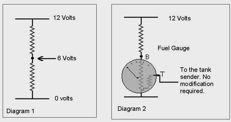
The basic principle used in the 12 volt conversion is as follows:-
If you connect two equal resistances, in series (one after the other)
across a voltage then the voltage at the junction of the two resistors
will be half the total voltage (see diagram 1).
If we now take one of the 6 volt components, for example the fuel gauge
and measure the resistance between the battery connection (marked B on
the case of the fuel gauge) and the earth return which is the body of
the fuel gauge we now place an equal resistor between the gauge and the
12 volt battery and that is all you do. The fuel gauge will now
run on 12 volt (see diagram 2).
You will need to repeat this for any 6 volt component which is now to
run on 12 volt. This includes the windscreen wiper and trafficators.
If I remember correctly my fuel gauge needed a 30 ohm 10 watt
resistor, but this will depend upon your gauge; where as the
trafficators and wipers only needed between 1 and 2 ohms
but a 50 watt resistor.
All the bulbs and the coil must be changed to 12 volt although the
resistor method can be used with the coil to retain the 6 volt coil.
There is no need to make any changes to the starter motor or the horn as
both of these will work more efficiently when 12 volts is put through
them and they will not suffer damage as they are for intermittent use
only.
The final part left is the cut-out which prevents the battery from
trying to drive the dynamo like a motor when the dynamo is not producing
volts.
I have been told that simply adding a resistor to the existing cut-out
following the scheme above will work although I personally have not
tried this. I have replaced the cut-out with a Diode (a diode is a one
way valve).
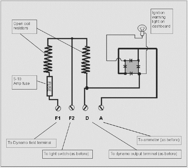
Which ever of the two methods used an additional resistor must be added
to the field supply to the dynamo (in the region of one ohm), to prevent
the 12 volts from cooking the field windings of the dynamo.
My original design used two resistors of 100 watt capacity but these
were not ‘man enough’ so I now use two lengths of electric heater
element. Electric heater elements (as used in a convector heater or fan
heater) are actually made from resistance wire which causes them the
heat up and are ideal to make low resistance/high wattage resistors.
This may seem crude but the same type of resistors are already used by
Austin.
The diode I have used comes in a package with four diodes, called a ‘bridge rectifier’ and normally used in Hi-Fi equipment to convert AC electrical current to DC. The type you need is 35 Amp 200 volt Single Phase Bridge Rectifier; these are available from RS Ltd. Two of the diodes (within the component) are used together and the other two allow the ignition warning light to be incorporated in the design. The symbol for a diode is as in diagram 3 and a bridge rectifier is shown in diagram 4.

I have used the bridge rectifier as it will cope with several hundred
volts at 30+ amps, more than any A7 dynamo is ever likely to produce,
and comes in a nice package which can easily be bolted to a metal heat
conductor to keep it cool.
I have temporarily removed the insides of a 60’s/70’s car cut-out and
voltage regulator to provide a housing for the diodes and resistors, a
photo with the cover removed is shown on the next page. The diode is
bolted to a piece of sheet aluminium which in turn is bolted to the car
bodywork.
The wiring diagram is given for Negative earth cars, for positive
earth cars the diode has to be wired in the opposite direction.
Everything else is the same.

To test the diode use a car battery and bulb; current from the +
terminal should flow through the diode connection which will eventually
go to the ‘D’ on the wiring diagram shown on the next page and light the
bulb up, It must not flow the other way as this will allow the battery
to drive the dynamo. Current must only flow from the dynamo to the
battery.
The diode type cut-out in the picture above does look very crude but
has served its purpose for nearly 12 months and has included the LE
JOGLE and trips to Holland and the midlands. In the near future I will
be making a proper housing which hopefully will look more like the
original. Until then my temporary housing will suffice.
I realise that this article sounds very involved and complicated but if
you take your time to think exactly what you have now and then look to
see how the modifications fit in they are actually quite simple. I am
also prepared to run a mini ‘teach-in’ for those who actually want to
convert their cars and will give what advice I can.
Its easier than you think, I took the opportunity to change the
trafficators to flashing indicators as I regularly use the car at night
and these are a lot safer so I made no modification to my trafficators.

Notes
The diagram above replaces the cut-out and follows the wiring of the old
system except originally two wires went to F2. The wire to the old F2
from the light switch still goes to F2 on the new system but the wire
from the dynamo field connection now goes to F1 on the new system.
The ignition light needs to be 12v 1 or 2 watt bulb, nothing
critical.
Once you have assembled the unit within the dotted line (excluding the
ignition light) it simply replaces the existing cut-out with little
change to the wiring.
This article written by Malcolm Watts, originally appeared in CA7C Seven Focus in Mar 2001 pp20-24.
See also: