Last updated: 3rd December 2024
Carburretor Compensation
Leafing through an old Motor Vehicle text book recently I stumbled on a cross section of a Zenith carburettor which made me think more about why we have two jets, rather than one, lurking in the bottom of the float chamber. When poking the jets out with a bit of wire and seeing that additionally there is a seemingly useless hole open to the atmosphere I have also been tempted to put a gasket over it. If you’ve ever felt the same, read on.
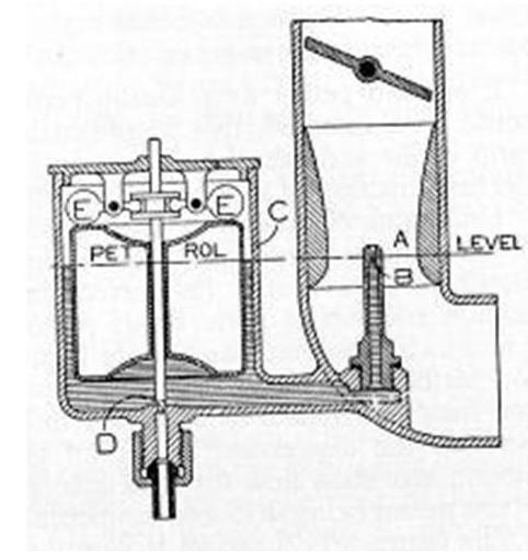
Simple (old motor cycle type) carburettors have single main jets and work in the fashion illustrated at Figure One. Their chief draw back, in larger applications, is that as engine size increases so do air and fuel flow rates and if you stay with fixed choke (air) and jet (petrol) sizes, as engine suction increases there will be an unavoidable tendency, largely due to the differing viscosity and densities of air and petrol, for the air/fuel mixture to become progressively richer, hence the need for some form of compensation, and the reason for the second jet.
Figure 1. Simple Carburettor
 In its simplest form this means letting proportionally more air
or less petrol, into the engine as the suction increases. Austin Seven Zenith
carburettors use what is known a the Bavery method and do this by reducing,
proportionately, the amount of petrol entering the choke in the manner
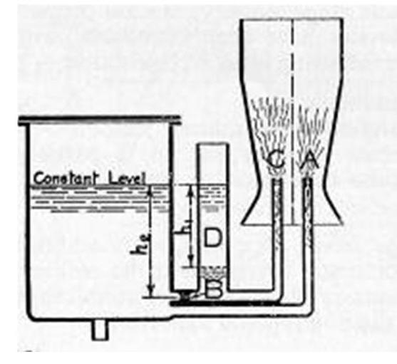
illustrated at Figure 2, where A is the Main Jet, B is the submerged
Compensating Jet and C is the Compensating Jet Delivery Tube.
The Main Jet is fed from the float chamber in the normal way, with the result that its own potion of air/fuel mixture becomes increasingly rich with increasing engine suction (choke pressure depression).
The Compensating Jet on the other hand is
fed from the Well, D, which is in direct communication with the atmosphere.
Figure 2. Compensation Principle

At very small throttle opening, the petrol in the Well is level with that in the
float chamber and there is no flow through the compensating jet, as the fuel
level in the Well and float chamber are equal and open to atmosphere.
As the
throttle is opened and increasing suction in the choke causes petrol to flow
from both the float chamber and Well, the level in the Well falls, due to the
Compensating Jet B, and the delivery at C is reduced such that the overall
mixture, entering the engine, is prevented from becoming too rich.
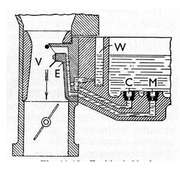
Figure 3. Zenith Carburettor
 Looking at the Zenith down draft carburettor in particular, which
represents the general features of the V type carburettor, Figure 3, C
is the Compensating Jet, not delivering directly into the Well as above,
but into an intermediate chamber formed in the Emulsion block, E.
The fuel pressure at E is therefore an intermediate between Well and choke pressure and depends on the size of the communicating holes, choke depression and the resistance of the communicating passage in the Emulsion Block, such that the amount of compensation depends largely on engine suction. It is also worthy of note that secondary suction effects are deliberately introduced into the choke by chamfering the emulsion outlet and use of the ‘distributor bar’, shown as the black dot adjacent to this outlet.
So keep your jets clear, clean all the connecting holes and don't put a gasket over the top of the well!
This article, written by Paul Newman, originally appeared in CA7C Seven Focus in March 2011, pp28-29.
See also: