Home
Page
welcome to our website
About Us
information about our Club
Contacts
our Officers and Committee
Events Diary
our events for the
months ahead
Event Reports
from the last four months
Member's Cars
a selection of
our active "Sevens"
Joys of being a 7'er
and a few stories
Do you fancy an Austin Seven?
advice on buying a "Seven"
Photo Gallery
of our past activities and
"Sevens" in close up
From the Past
Items from 1920/30s
magazines
Registration Marks
in the UK from 1903
Help at the roadside
fuel and electrical problems
Austin Seven Journal
advice for Austin Agents
& Service Depots
Austin Seven
Handbooks
information for the
new owner
Technical Articles
our Members help you
with various tasks
Austin Big Seven
Sixlite & Forlite
Magazine Articles
relevant to Sevens
Road Tests
for the most popular "Sevens"
Parts and Services
sources of spares etc
Quick Tips
a few handy ideas
Other Articles
of interest, not technical
Austin Seven Books
some of the books available
A7CA and FBHVC
CA7C is an active supporter
Links to other Austin
Seven Sites
Website Policy
on advertisements and links
Last updated:
23 September, 2023
12v Conversion - another way
Those who know my car (once seen never forgotten!) will be aware that
it runs 12Volts. As a special it was cheap and easy to start from the
beginning with 12Volts, both for electrical reasons and cheapness of
parts!
The 12Volt conversion used a popular “solid state” regulator which may
be familiar to some of you. Basically it monitored and regulated the
charge voltage and thus the current by electronic means and therefore
worked very well. In fact the ammeter always showed a small (1A) charge
no matter what the load on the system was. However several
conversations with Club members and some internet forum discussions gave
rise to some concerns about the durability of the device.
Being a solid state device it is susceptible to damage from “spikes”.
Jump starting or a flat battery are know to be fatal to the device! The
fear was that a breakdown miles from home would be “unfixable”. The
solid state device was “potted” and thus fault finding is impossible and
the dynamo had been converted to 2 brush operation. Both of these facts
could cause a headache for roadside repair jobs!
I wanted to go back to a 3 brush dynamo with some form of adjustable
charge control to allow a bit more selection than the standard half or
full charge. Internet discussions came up with several resistors rigged
up to give a “switchable range to replace the standard half charge
resistance. This led to the logical conclusion of a rheostat! Given
the standard half charge resistance value and the 3 ohms or so for the
field coils a value of 0 -5 ohms was chosen for the rheostat, which was
thought to be good for a 12 volt system. The worse case scenario for
the rheostat would probably be 12Volts flowing through the field, giving
something like 4 amps and 48 watts flowing in the field at the “full
charge” setting (in reality this probably won't arise). Because of this
a suitable size rheostat needs to be used. I managed to buy a 150watt
item off ebay from Canada as ex military old stock for about £23 air
freighted to the UK in about 3 days! Be cautious though as a similar
spec bought from an electrical supplier in the UK can cost a lot more
than that!
All that is required is to fit this rheostat in place of the standard
half charge resistance i.e. across the D and F terminals. You can now
manually control the current flowing in the field coils and therefore
alter the charge rate. I mounted the rheostat on the bulkhead and use a
shaft through to the dash to allow adjustment from the drivers seat,
although on a special this is easier than it may be on an original car.
You can and should still use the 3rd brush to limit charging and
remember that between 8-10 amps seems to be the sensible draw from the
C35 dynamo, which is no problem at 12V with 36 Watt headlight bulbs.
Of course this leaves the cut out! An essential device to prevent the battery trying to turn the engine over via the dynamo! 12v Cut outs seemed to be difficult and expensive, so I decided after being offered much advice that a Schottky diode would be the cheap and much simpler alternative to the electro mechanical cut out. They are available in all manner of specs, but the one I settled on has a 30A rating with a reverse breakdown voltage of 45 Volts.
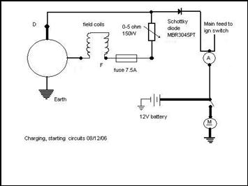 Basically
the Schottky diode allows current to pass to the battery via the ammeter
, but does not allow current to flow back from the battery (technically
a small amount does flow backwards). Thus it does an excellent job
of replacing the cut out and is relatively cheap, so you can carry a spare or 2! You should ensure that it is
purchased with the correct silicone mounting pad to allow it to be heat
sunk to a piece of aluminium or a bulkhead to dissipate the heat and
prevent premature failure. A battery master, or isolator,
switch (M), is a wise fitment
too as the small leakage current can cause problems after long periods
of time, and I am informed that the failure mode of the Schottky diode
is short circuit so it no longer acts as a diode and an isolator switch
would prevent any damage!
Basically
the Schottky diode allows current to pass to the battery via the ammeter
, but does not allow current to flow back from the battery (technically
a small amount does flow backwards). Thus it does an excellent job
of replacing the cut out and is relatively cheap, so you can carry a spare or 2! You should ensure that it is
purchased with the correct silicone mounting pad to allow it to be heat
sunk to a piece of aluminium or a bulkhead to dissipate the heat and
prevent premature failure. A battery master, or isolator,
switch (M), is a wise fitment
too as the small leakage current can cause problems after long periods
of time, and I am informed that the failure mode of the Schottky diode
is short circuit so it no longer acts as a diode and an isolator switch
would prevent any damage!
And that’s it! All you actually need for the 12Volt conversion is the
schottky diode to act as cut out, total cost £1.71! You could just put
an extra 1 ohm series resistance in the field to limit the current , but
the rheostat conversion gives you that bit extra fine adjustment! Of
course bulbs will need changing and a 12Volt battery purchased, and a
resistor is needed to limit voltage to the petrol gauge if you have
one. The conversion is as easy to fault find or repair as the standard
system with no complicated circuitry at all.
Parts: 1 x Schottky barrier rectifier part no: MBR3045PT; 1 x 0-5 ohm 150W rheostat; Assorted lengths of cabling; Adjuster knob and shaft for remote adjustment
This article, written by Steve Martin, originally appeared in CA7C Seven Focus in Mar 2007 p16-17.
See also: