Home
Page
welcome to our website
About Us
information about our Club
Contacts
our Officers and Committee
Events Diary
our events for the
months ahead
Event Reports
from the last four months
Member's Cars
a selection of
our active "Sevens"
Joys of being a 7'er
and a few stories
Do you fancy an Austin Seven?
advice on buying a "Seven"
Photo Gallery
of our past activities and
"Sevens" in close up
From the Past
Items from 1920/30s
magazines
Registration Marks
in the UK from 1903
Help at the roadside
fuel and electrical problems
Austin Seven Journal
advice for Austin Agents
& Service Depots
Austin Seven
Handbooks
information for the
new owner
Technical Articles
our Members help you
with various tasks
Austin Big Seven
Sixlite & Forlite
Magazine Articles
relevant to Sevens
Road Tests
for the most popular "Sevens"
Parts and Services
sources of spares etc
Quick Tips
a few handy ideas
Other Articles
of interest, not technical
Austin Seven Books
some of the books available
A7CA and FBHVC
CA7C is an active supporter
Links to other Austin
Seven Sites
Website Policy
on advertisements and links
Last updated:
23 September, 2023
How it Works - the Cut-out
The charging system of the Austin Seven primarily consists of a dynamo to produce an electric current and a battery in which to store the charge. In between these two is an automatic switch, known as a Cut-out. Without the cut-out, the battery would be charged whenever the dynamo is rotated sufficiently fast by the engine, but would be rapidly discharged by trying to operate the dynamo as a motor when the engine revs are not high enough – particularly when the engine is stationary. Note that the ignition switch does NOT disconnect the dynamo from the battery; it only disconnects the ignition circuit itself, (plus a few auxiliary devices such as stop lights). The ignition switch is therefore not relevant to the cut out operation or charging circuit.
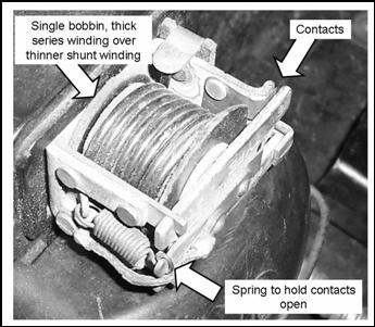
There have been a number of variants during the period over which the cars were manufactured. However, they all have the same function and all have very similar operation. Each Cut-out has a set of spring loaded contacts mounted on a mechanical rocker, known as an armature, plus two electromagnets which are arranged so as to pull and push on this armature. One electromagnet is connected between the dynamo output terminal “D” and earth, (the “shunt” winding”), and the other, (the “series” winding) is connected in series with the battery usually marked “A” and the cut-out contacts. Note that, depending on cut-out type, these windings may be on separate bobbins or combined on one bobbin. Irrespective of type, the shunt winding is composed of many turns of thin wire, whilst the series winding is very few turns of substantially thicker wire.
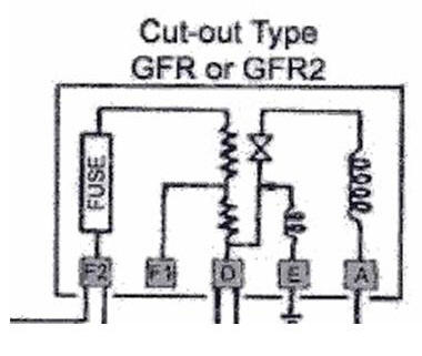
Example cut-out circuit

With the engine stationary, it is necessary for the battery to be disconnected from the dynamo, to prevent the “motor” action described above. Hence, the contacts must be open. This is the resting state of the cut-out.
As the engine is started and the revs increased, the dynamo output voltage will rise. This output voltage appears across the shunt winding, making it act as an electromagnet. As the series winding has one end connected to an open contact, it plays no part at this stage. Eventually, (at fast tickover), the dynamo voltage will reach a value that would be high enough to prevent current flowing from the battery to the dynamo, but would allow current to flow from the dynamo to the battery – the normal charging method. The shunt winding is arranged so that when the dynamo output voltage reaches this value, it produces a sufficiently strong magnetic field to pull on the armature overcoming the spring force and close the contacts. The battery is now being charged. For 6V systems, this should occur at approximately 6.5V; for 12V, this occurs at 13.5V. As soon as the contacts are closed, the shunt winding is now also connected across the battery. This gives a latching action as the battery now also supplies current for the shunt winding. In this state, the contacts would still be pulled shut until the battery voltage dropped to a low level irrespective of the dynamo output, as the electromagnet is now being operated by the battery.
Consequently, it is necessary to counteract this force so that the spring can pull the contacts apart to disconnect the battery. This is the function of the second or “series” winding.
The Series winding produces a force on the armature which is proportional to the current flowing either to or from the battery, and which changes direction with the direction of current flow. When the battery is being charged, the force acts to add to the pulling force from the shunt winding, causing the contacts to be held firmly shut. However, when the dynamo output falls so that there is a current from the battery to the dynamo, the force is now in the opposite direction and opposes that of the shunt winding. When the force from the series winding equals that of the shunt, then the armature is released for the spring to open the contacts.
If the engine is stopped at this point, the battery is safely disconnected from the dynamo. If the revs rise, the force from the shunt winding will close the contacts again.
This can be seen in operation from the behaviour of the ammeter. With all other electrical loads off, (note that the ammeter measures all current flow from the battery, not just that to the dynamo), and the engine running at a fast tickover, the ammeter will settle in the charging side of the scale. When the revs are allowed to drop, the ammeter will move to the discharge side and then suddenly fall back nearer to zero. This sudden fall back occurs when the series winding has sufficient current flowing in the discharge direction to counteract the closing force from the shunt winding and the contacts are opened. The charging warning light will operate at the same time. No current flows to the dynamo; the remaining discharge shown is actually the current required by the ignition circuit.
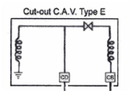

Type E 1922-1923
Type CF1 1924-1931

Type CF3 1931-1933
Type GFR or
GFR2
1934-1937
This article, written by Geoff Hardman, originally appeared in CA7C Seven Focus in Nov 2006 pp6-8.